Light sensor circuit using ldr pdf
Abstract: LDR light sensor sensor LDR ldr sensor led ldr sensor dark light sensor using LDR circuit for pseudo random generator LDR Datasheet ldr sensor FOR LIGHT SENSING LDR night light circuit Text: Switch is set to the random mode, the Switch’s light sensor kicks in.
When light falls on LDR then the resistance of LDR will decrease and approximate equal to 10 ohms.(b) Light Sensor Let 9V-DC is flowed in the circuit. The 100 kilo-ohms is connected to minimise the current flow to the battery. 9V DC comes from 470 ohms resistance and passes through an LED to the collector end of the BC-547 transistor. When light falls on the LDR. When DC voltage comes through
Dark sensor using two transistors ABSTRACT- This works same as the other dark detector circuit INTRODUCTION- It is a very simple experiment for Arduino amateurs, kids and
Ldr Circuit Diagram – August 26, 2018 by luqman. Post tagged: ldr circuit diagram, ldr circuit diagram 230v, ldr circuit diagram 230v pdf, ldr circuit diagram for street light, ldr circuit diagram on breadboard, ldr circuit diagram pdf, ldr circuit diagram using 555, ldr circuit diagram with arduino, ldr circuit diagram with led, ldr circuit
Light sensor using ldr, photodiode and phototransistor, a light sensor is a passive sensor that is used to indicate the intensity of the light by examining the radiant energy that exists in a certain range of frequencies. Automatic led emergency light circuit, an automatic led emergency light circuit is designed to turn on when there is no adequate lighting or if the power supply is cut off
Fig.2.Sensor Arrangement A. LDR (Light Dependent Resistor) LDRs or light dependent resistor are very useful especially light or dark sensor circuit .Normally the resistance of LDR is very high, sometimes as high as 1000000 ohms, but when they are illuminated with light resistance, drops dramatically. A photo resistor are light dependent resistor (LDR) is resistor whose resistance …
Light detectors are one of the most popular sensor and they are commonly found in many real-world applications. They are widely used by electronic hobbyists and projects because they are practical and intriguing yet surprising easy to construct.
Queensland University of Technology Page 3 Step 1 : Pluging and using the light sensor Building the circuit on the breadboard. The light sensor has to be plugged in an analogical input such as AN0-4.
A light detector component, we often to use a photo resistor or LDR = Light Dependent Resistor is variable resistance by light. This circuit we take a LDR acts as light receiver from sunlight. Changing a resistance applied to any electronic components as we need them to used.
In this project we will monitor the room temperature using a LDR_NSL19_M51 light dependant resistor (LDR) and 4Duino. The resistance of the LDR varies significantly with ambient light hence it can detect surrounding light intensity changes in real time.
2/01/2019 · A calibration of the LDR sensors will be done, based on a photodiode pyranometer. Thus, statistical analyzes of regressions between the collected points are done from the data collected via
For this we use a tiny circuit that pushes power through the LDR. Since the LDR decreases its resistance as light increases, more “power” will pass through it to the Analog pin, which results in the Arduino “reading” a higher value.
Design and Implementation of Automatic Street Light Control System using Light Dependent Resistor Gouthami. C variation in voltage across the LDR circuit, due to changes in the illumination of sunlight. The real time, ON time and OFF time setting is done using the keyboard and LCD display. The change in voltage across LDR circuit and the ON and OFF time settings are analyzed by the
2/08/2017 · How to make Dark Sensor with LDR dark/light sensor using transistor ldr sensor شرح ldr circuit photocell sensor what is ldr ldr sensor pdf light dependent resistor
How an LDR (Light Dependent Resistor) Works Kitronik

sensor LDR datasheet & applicatoin notes Datasheet Archive
This kind of sensor is commonly used in light sensor circuits in open areas, to control street lamps for example. Another possible use is in spectroscopic apparatus [1].
Dark sensor using LDR on breadboard 1 LDR (Light Dependent Resistor) Light Dependent Resistor or Photoresistor, which is a passive electronic component, basically a resistor which has a resistance that varies depending of the light intensity. A photoresistor is made of a high resistance semiconductor that absorbs photons and based on the quantity and frequency of the absorbed …
27/09/2016 · So that when it’s dark the lamps turn on, and turns off when ambient light level increases (not using the motion detection for the second circuit). I couldn’t find a circuit diagram for this sensor and I’m also not sure it’s ok to add a relay somewhere in a circuit like that.
The light sensor for a lux meter can be one of several different types of sensors, including photodiodes and phototransistors, but the easiest to use and often the most readily available type of sensor is a photoresistor or light dependent resistor (LDR). As you would expect, the resistance of an LDR changes as the amount of light falling on it changes. If you can measure the resistance of the
Automatic Street Light Control System is a simple yet powerful concept, which uses transistor as a switch. By using this system manual works are 100% removed. It automatically switches ON lights when the sunlight goes below the visible region of our eyes. This is done by a sensor called Light Dependant Resistor (LDR) which senses the light actually like our eyes. It automatically switches …
The example circuit used in various situations, such as control lamps or other device that needs to be turned off when the daylight. It is based on LDR (Light Dependent Resistor) is a special resistor that varies its electrical resistance according to the amount of light falling on its surface.
Monitoring the output of a light-dependent resistor, or photoresistor, allows the Arduino to know how light or dark it is. When the light falls below a certain level, the Arduino turns on a couple of LEDs. A light-dependent resistor, or photoresistor, is a sensor whose resistance decreases as the
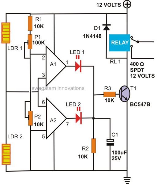
The circuit shown in figure 1 is a very simple light sensor circuit that will activate an LED when the LDR in the circuit receives light. The circuit shown in figure 2 is using a relay at its output and when light falls on the LDR it will activate the relay. switch and hence any AC and DC appliance connected with the relay will become activated. Working of the circuit is simple, when the

1. Introduction. The light dependent resistor (LDR) is a sensor whose resistance decreases when light impinges on it. This kind of sensor is commonly used in light sensor circuits in open areas, to control street lamps for example.
2/05/2016 · The circuit should work as follows: when there is sufficient light falling on the LDR, the transistor should be in saturation and the LED should be lit and when there is not sufficient light falling on the LDR then that transistor is in cutoff and the LED is not lit and the buzzer should sound.
Abstract: LDR light sensor sensor LDR ldr sensor led ldr sensor dark light sensor using LDR circuit for pseudo random generator LDR Datasheet ldr sensor FOR LIGHT SENSING LDR night light circuit Text: Light Switch using the 8-pin PIC12CXXX series of 8 pin, 8 bit microcontrollers.
Using this in series with the LDR we can work out how much resistance the LDR is giving out thus whether it is light or dark. To get the light sensor circuit built correctly follow the steps below or check out the circuit diagram right underneath the steps.
KA A DC DC Converter IC DSMCZ from ldr sensor datasheet pdf , source:dsmcz.com Unique Photos Of Ldr Sensor Datasheet Pdf – Through the thousand Figure on the web with regards to ldr sensor datasheet pdf, we all filter the most libraries along with perfect image resolution absolutely for you all, and now this photographs ,in fact, one among
Light Sensor & E.T Microchip Technology
This optoelectronic device is mostly used in light varying sensor circuit, and light and dark activated switching circuits. Some of its applications include camera light meters, street lights, clock radios, light beam alarms, reflective smoke alarms, and outdoor clocks.
Figure 1 shows an ambient light sens or without the epoxy filter and figure 2 sh ows the sensor with the epoxy filter. Wit h Wit h this epoxy filter the bandwidth (λ 0.5 ) …
But, Light Dependent Resistor (LDR) or photoresistor is a special type of light sensor which is used in this automatic light sensor circuit. These light dependent resistors are passive and doesn’t produce any electrical energy. – celpip study guide listening and speaking LDR sensor senses the intensity of light from the sun, the system will turn off both street lights and PIR sensor. Lastly, the system will loop to the initial condition.
Here is my new simple Electronics project about Automatic Street Light Control System or Dark Sensor. it is a simple and powerful concept , which uses transistor ( BC 547 NPN) as a switch to switch ON and OFF the street light system automatically .
An LDR is exposed to the light reflected from these squares. The LDR is part o f a circuit like that on p. 75, and the output voltage is se nt to a comparator.
The circuit shown above shows a simple way of constructing a circuit that turns on when it goes dark. In this circuit the LDR and the other Resistor form a simple ‘Potential Divider’ circuit, where the centre point of the Potential Divider is fed to the Base of the NPN Transistor.
intensity by using a light sensor. During night time (when the light illuminated on LDR decreases), the LDR exhibits a very The 555 timer output is used to control the triggering of load through a TRIAC. This Automatic night light with one LED circuit is simple, interesting and easy to The diagram shows a proposed placement of the elements (it is 200%). Turn your security lighting or task
Ldr Circuit Diagram Arduino Light Sensor Circuit Using Ldr Ldr Circuit Diagram This Is The Light Fence Schematic Diagram Uses Ldr, This, Simple Ldr Circuit Diagram Light Activated Switch Using Ldr Sensor – Youtube
The resistance of the LDR sensor changes with the change in intensity of light falling on LDR. This sensor output is given to IC 555 timer connected in bistable mode. The o/p of the IC 555 timer is used to control the prompting of load through a TRIAC. Hence, this circuit switches on the load in the sunset and switches off the load in the sun rise automatically.
useful tool in a light/dark circuits. A LDRs can have a variety of resistance and functions. For example it can be used to turn on a light when the LDR is in darkness or to turn o˜ a light when the LDR is in light. It can also work the other way around so when the LDR is in light it turns on the circuit and when it’s in darkness the resistance increase and disrupts the circuit. How it Works
Using the full streetlight efficiency while there is no any kind of transportation on the road is a waste of power, so this project is designed to work only when a car or human crossed the road. And this will happened with the help of motion sensors, also light sensors will be added but to activate the system to be ready for the motion sensors signals which will turn on the LED streetlights
This LDR circuit diagram shows how you can make a light detector. An LDR or “Light Dependent Resistor” is a resistor where the resistance decreases with the strength of the light.
A photoresistor (or light-dependent resistor, LDR, or photo-conductive cell) is a light-controlled variable resistor. The resistance of a photoresistor decreases with increasing incident light intensity; in other words, it exhibits photoconductivity .
Tagged with: Tw eet 1 Like 17 1 Share LDR MINI BREADBOARD PHOTODIODE PHOTOTRANSISTOR About Sagar Sapkota Sagar Sapkota is a sole entrepreneur living in Espoo. 2012 at 8:05 am .dark sensor.WATCH THE VIDEO: EXPERIMENT 4: RELAY TEST Make dark sensor using relay. 2013 at 6:55 pm How to enhance the dark/light sensor into a miniproject Reply Avijit January 18. latch circuit.
Induscon 2018 Low-Cost Solar Irradiance Meter using LDR
Watch video · A simple dark detector alarm circuit diagram using 555 timer IC and LDR. This LDR circuit detects the light in surrounding and upon detecting dark, and switch on the alarm. This LDR circuit detects the light in surrounding and upon detecting dark, and switch on the alarm.
DOWNLOAD .PDF. Recommend Documents. automatic street light using LDR sensor . mini project for diploma students this is very use full . Automatic Street Light Controller . Automatic Street Light Controller. Automatic Street Light Using Ic555 and Ldr(Student Name Albin) Physics Project. Automatic Street Light Using PIC Microcontroller . street lights are switched on for the whole night …
Infrared Sensor Application Note Infrared Sensor Application Note, Single-Rail Amplifier Circuit for Infrared Gas Sensors, pdf file LDR LIGHT/DARK ACTIVATED RELAY SWITCH using an LDR to turn on a relay, pdf file
The term LDR is known by many names such as a light dependent resistor, photo resistor, photo conductor, the photocell. The term photocell is most widely used in data sheets as well as instruction sheets for domestic gear.
Dual Axis Solar Tracking System using 5-LDR sensor as the intensity of light changes making the sensor to work effectively in sunny as well as in cloudy weather. The principle used behind the designing of sensor is Voltage Divider Law. Fig.3 shows the simple series circuit. The applied voltage is divided between two resistors, out of which voltage across one resistor can be used as an
31/12/2018 · – light sensor switch circuit electroschematics this light sensor switch circuit allows the automatic connection of a lamp when the light is low at nightfall systematic diagram is needed light sensor circuit working of the circuit is simple when the photoresistor or ldr receives light it will switch on the transistor 2n2222 when transistor be e on it will .
26/07/2011 · So I used a LDR sensor and I connected one pin to the VCC and the other to the micro-controller so that when it detects light, it short circuits and give 5 volt to the controller and when there is no light, the resistance of the LDR becomes very high and gives zero voltage to the controller.
So voltage across LDR changes with intensity of light. Voltage across the LDR is given to the positive terminal of a comparator. Now a reference voltage is required to compare with the voltage across LDR. That reference voltage is made by using the pot or preset. So this preset can be used to adjust the sensitivity of the circuit. Next is the comparator made using LM358 op-amp which compares
The time-honored tradition is to use a circuit with a CdS photoresistor, sometimes called a photocell or LDR, for “light-dependent resistor.” (Circuit Example 1, Example 2.) Photoresistors are reliable and cost about each, but are going away because they contain cadmium, a toxic heavy metal whose use is increasingly regulated.
Circuit Diagram – Smart Brightness Control. Let’s have a look at the sensors first. Sensors – LDR and DHT11. In order to detect the intensity of light, we use a sensor called an LDR (Light …
Arduino – Playing with a light sensitive resistor (LDR)

50 Awesome Light Sensor Switch Circuit Diagram Circuits
Light sensor using Photo Transistor. Ask Question 5. 5. How can I design a circuit which utilizes a photo-transistor to make a light sensitive switch that is when there is no light in room, the led connected to the photo-transistor lights up and when there is light in room, the led connected to Phototransistor turns off? Any schematic or circuit diagram would be really helpful. Here is the
The operation of this type of light sensor circuit can also be reversed to switch the relay “ON” when the light level exceeds the reference voltage level and vice versa by reversing the positions of the light sensor LDR and the potentiometer VR1. The potentiometer can be used to “pre-set” the switching point of the differential amplifier to any particular light level making it ideal as
LDR Circuit Diagram Build Electronic Circuits December 18th, 2018 – This LDR circuit diagram shows how you can make a light detector An LDR or “Light Dependent Resistor†is a resistor
Ldr Circuit Diagram Light Activated Switch Using Ldr Sensor – Youtube; Ldr Circuit Diagram Light Activated Switch Using Ldr Sensor – Youtube
5 4. Usage 4.1 With Arduino Follow these simple steps to build a Grove circuit using the light sensor: 4.1.1 Hardware connection When using the module in conjunction with an Arduino or a Seeeduino, use …
Circuit Diagram and working of Automatic Street Light Controller Switch Using Relays and LDR. It automatically turns on and off street lights.
The circuit of light operated lamp switch utilizes a diac and a triac as semiconductor and LDR as sensor. LDR is a type of variable resistor and change its value according to intensity of light fall on its surface. At dark its resistance increases up to mega ohms, which does not …
Automatic Night Lamp using LDR electroSome

OPT3001 Ambient Light Sensor (ALS) datasheet (Rev. C)
Grove Light Sensor(P) User Manual – Mouser Electronics


Light Sensor Circuit Circuit Diagram
https://en.wikipedia.org/wiki/Photoresistor
use a PIR sensor as a light sensor switch Electronics Forums
ielts 8 listening test 1 pdf – Simple Light Sensor Circuit with Applications ElProCus
Ldr Sensor Datasheet Pdf Beautiful Ka A Dc Dc Converter Ic
Light dependent resistor(LDR) physics investigatory project
Dark Sensor Using Transistor Phototransistor and Photodiode
Ldr Circuit Diagram Automatic Night Lamp Using Ldr
Simple Light Sensor Circuit with Applications ElProCus
Ldr Circuit Diagram Light Activated Switch Using Ldr Sensor – Youtube; Ldr Circuit Diagram Light Activated Switch Using Ldr Sensor – Youtube
5 4. Usage 4.1 With Arduino Follow these simple steps to build a Grove circuit using the light sensor: 4.1.1 Hardware connection When using the module in conjunction with an Arduino or a Seeeduino, use …
2/08/2017 · How to make Dark Sensor with LDR dark/light sensor using transistor ldr sensor شرح ldr circuit photocell sensor what is ldr ldr sensor pdf light dependent resistor
Watch video · A simple dark detector alarm circuit diagram using 555 timer IC and LDR. This LDR circuit detects the light in surrounding and upon detecting dark, and switch on the alarm. This LDR circuit detects the light in surrounding and upon detecting dark, and switch on the alarm.
Fig.2.Sensor Arrangement A. LDR (Light Dependent Resistor) LDRs or light dependent resistor are very useful especially light or dark sensor circuit .Normally the resistance of LDR is very high, sometimes as high as 1000000 ohms, but when they are illuminated with light resistance, drops dramatically. A photo resistor are light dependent resistor (LDR) is resistor whose resistance …
In this project we will monitor the room temperature using a LDR_NSL19_M51 light dependant resistor (LDR) and 4Duino. The resistance of the LDR varies significantly with ambient light hence it can detect surrounding light intensity changes in real time.
The circuit shown above shows a simple way of constructing a circuit that turns on when it goes dark. In this circuit the LDR and the other Resistor form a simple ‘Potential Divider’ circuit, where the centre point of the Potential Divider is fed to the Base of the NPN Transistor.
For this we use a tiny circuit that pushes power through the LDR. Since the LDR decreases its resistance as light increases, more “power” will pass through it to the Analog pin, which results in the Arduino “reading” a higher value.
Dark sensor using two transistors ABSTRACT- This works same as the other dark detector circuit INTRODUCTION- It is a very simple experiment for Arduino amateurs, kids and
LDR Circuit Diagram Build Electronic Circuits December 18th, 2018 – This LDR circuit diagram shows how you can make a light detector An LDR or “Light Dependent Resistor†is a resistor
A light detector component, we often to use a photo resistor or LDR = Light Dependent Resistor is variable resistance by light. This circuit we take a LDR acts as light receiver from sunlight. Changing a resistance applied to any electronic components as we need them to used.
Ldr Circuit Diagram – August 26, 2018 by luqman. Post tagged: ldr circuit diagram, ldr circuit diagram 230v, ldr circuit diagram 230v pdf, ldr circuit diagram for street light, ldr circuit diagram on breadboard, ldr circuit diagram pdf, ldr circuit diagram using 555, ldr circuit diagram with arduino, ldr circuit diagram with led, ldr circuit
DOWNLOAD .PDF. Recommend Documents. automatic street light using LDR sensor . mini project for diploma students this is very use full . Automatic Street Light Controller . Automatic Street Light Controller. Automatic Street Light Using Ic555 and Ldr(Student Name Albin) Physics Project. Automatic Street Light Using PIC Microcontroller . street lights are switched on for the whole night …
Automatic Street Light Controller Using Relays and LDR
sensor LDR datasheet & applicatoin notes Datasheet Archive
A light detector component, we often to use a photo resistor or LDR = Light Dependent Resistor is variable resistance by light. This circuit we take a LDR acts as light receiver from sunlight. Changing a resistance applied to any electronic components as we need them to used.
Monitoring the output of a light-dependent resistor, or photoresistor, allows the Arduino to know how light or dark it is. When the light falls below a certain level, the Arduino turns on a couple of LEDs. A light-dependent resistor, or photoresistor, is a sensor whose resistance decreases as the
Fig.2.Sensor Arrangement A. LDR (Light Dependent Resistor) LDRs or light dependent resistor are very useful especially light or dark sensor circuit .Normally the resistance of LDR is very high, sometimes as high as 1000000 ohms, but when they are illuminated with light resistance, drops dramatically. A photo resistor are light dependent resistor (LDR) is resistor whose resistance …
Ldr Circuit Diagram Arduino Light Sensor Circuit Using Ldr Ldr Circuit Diagram This Is The Light Fence Schematic Diagram Uses Ldr, This, Simple Ldr Circuit Diagram Light Activated Switch Using Ldr Sensor – Youtube
When light falls on LDR then the resistance of LDR will decrease and approximate equal to 10 ohms.(b) Light Sensor Let 9V-DC is flowed in the circuit. The 100 kilo-ohms is connected to minimise the current flow to the battery. 9V DC comes from 470 ohms resistance and passes through an LED to the collector end of the BC-547 transistor. When light falls on the LDR. When DC voltage comes through
The resistance of the LDR sensor changes with the change in intensity of light falling on LDR. This sensor output is given to IC 555 timer connected in bistable mode. The o/p of the IC 555 timer is used to control the prompting of load through a TRIAC. Hence, this circuit switches on the load in the sunset and switches off the load in the sun rise automatically.
Dark sensor using LDR on breadboard 1 LDR (Light Dependent Resistor) Light Dependent Resistor or Photoresistor, which is a passive electronic component, basically a resistor which has a resistance that varies depending of the light intensity. A photoresistor is made of a high resistance semiconductor that absorbs photons and based on the quantity and frequency of the absorbed …
So voltage across LDR changes with intensity of light. Voltage across the LDR is given to the positive terminal of a comparator. Now a reference voltage is required to compare with the voltage across LDR. That reference voltage is made by using the pot or preset. So this preset can be used to adjust the sensitivity of the circuit. Next is the comparator made using LM358 op-amp which compares
Smart LCD Brightness Control using Arduino and LDRUse
Light dependent resistor(LDR) physics investigatory project
Using the full streetlight efficiency while there is no any kind of transportation on the road is a waste of power, so this project is designed to work only when a car or human crossed the road. And this will happened with the help of motion sensors, also light sensors will be added but to activate the system to be ready for the motion sensors signals which will turn on the LED streetlights
Watch video · A simple dark detector alarm circuit diagram using 555 timer IC and LDR. This LDR circuit detects the light in surrounding and upon detecting dark, and switch on the alarm. This LDR circuit detects the light in surrounding and upon detecting dark, and switch on the alarm.
Design and Implementation of Automatic Street Light Control System using Light Dependent Resistor Gouthami. C variation in voltage across the LDR circuit, due to changes in the illumination of sunlight. The real time, ON time and OFF time setting is done using the keyboard and LCD display. The change in voltage across LDR circuit and the ON and OFF time settings are analyzed by the
For this we use a tiny circuit that pushes power through the LDR. Since the LDR decreases its resistance as light increases, more “power” will pass through it to the Analog pin, which results in the Arduino “reading” a higher value.
5 4. Usage 4.1 With Arduino Follow these simple steps to build a Grove circuit using the light sensor: 4.1.1 Hardware connection When using the module in conjunction with an Arduino or a Seeeduino, use …
Ldr Circuit Diagram – August 26, 2018 by luqman. Post tagged: ldr circuit diagram, ldr circuit diagram 230v, ldr circuit diagram 230v pdf, ldr circuit diagram for street light, ldr circuit diagram on breadboard, ldr circuit diagram pdf, ldr circuit diagram using 555, ldr circuit diagram with arduino, ldr circuit diagram with led, ldr circuit
The resistance of the LDR sensor changes with the change in intensity of light falling on LDR. This sensor output is given to IC 555 timer connected in bistable mode. The o/p of the IC 555 timer is used to control the prompting of load through a TRIAC. Hence, this circuit switches on the load in the sunset and switches off the load in the sun rise automatically.
Simple Light Detector With Sensitivity Control 7 Steps
Light Sensor including Photocell and LDR Sensor
In this project we will monitor the room temperature using a LDR_NSL19_M51 light dependant resistor (LDR) and 4Duino. The resistance of the LDR varies significantly with ambient light hence it can detect surrounding light intensity changes in real time.
A photoresistor (or light-dependent resistor, LDR, or photo-conductive cell) is a light-controlled variable resistor. The resistance of a photoresistor decreases with increasing incident light intensity; in other words, it exhibits photoconductivity .
Fig.2.Sensor Arrangement A. LDR (Light Dependent Resistor) LDRs or light dependent resistor are very useful especially light or dark sensor circuit .Normally the resistance of LDR is very high, sometimes as high as 1000000 ohms, but when they are illuminated with light resistance, drops dramatically. A photo resistor are light dependent resistor (LDR) is resistor whose resistance …
So voltage across LDR changes with intensity of light. Voltage across the LDR is given to the positive terminal of a comparator. Now a reference voltage is required to compare with the voltage across LDR. That reference voltage is made by using the pot or preset. So this preset can be used to adjust the sensitivity of the circuit. Next is the comparator made using LM358 op-amp which compares
5 4. Usage 4.1 With Arduino Follow these simple steps to build a Grove circuit using the light sensor: 4.1.1 Hardware connection When using the module in conjunction with an Arduino or a Seeeduino, use …
Dark sensor using LDR on breadboard 1 LDR (Light Dependent Resistor) Light Dependent Resistor or Photoresistor, which is a passive electronic component, basically a resistor which has a resistance that varies depending of the light intensity. A photoresistor is made of a high resistance semiconductor that absorbs photons and based on the quantity and frequency of the absorbed …
Ldr Circuit Diagram Arduino Light Sensor Circuit Using Ldr Ldr Circuit Diagram This Is The Light Fence Schematic Diagram Uses Ldr, This, Simple Ldr Circuit Diagram Light Activated Switch Using Ldr Sensor – Youtube
Light sensor using ldr, photodiode and phototransistor, a light sensor is a passive sensor that is used to indicate the intensity of the light by examining the radiant energy that exists in a certain range of frequencies. Automatic led emergency light circuit, an automatic led emergency light circuit is designed to turn on when there is no adequate lighting or if the power supply is cut off
Dark sensor using two transistors ABSTRACT- This works same as the other dark detector circuit INTRODUCTION- It is a very simple experiment for Arduino amateurs, kids and
useful tool in a light/dark circuits. A LDRs can have a variety of resistance and functions. For example it can be used to turn on a light when the LDR is in darkness or to turn o˜ a light when the LDR is in light. It can also work the other way around so when the LDR is in light it turns on the circuit and when it’s in darkness the resistance increase and disrupts the circuit. How it Works
2/08/2017 · How to make Dark Sensor with LDR dark/light sensor using transistor ldr sensor شرح ldr circuit photocell sensor what is ldr ldr sensor pdf light dependent resistor
Abstract: LDR light sensor sensor LDR ldr sensor led ldr sensor dark light sensor using LDR circuit for pseudo random generator LDR Datasheet ldr sensor FOR LIGHT SENSING LDR night light circuit Text: Light Switch using the 8-pin PIC12CXXX series of 8 pin, 8 bit microcontrollers.
31/12/2018 · – light sensor switch circuit electroschematics this light sensor switch circuit allows the automatic connection of a lamp when the light is low at nightfall systematic diagram is needed light sensor circuit working of the circuit is simple when the photoresistor or ldr receives light it will switch on the transistor 2n2222 when transistor be e on it will .
2 Comments